 how-to
What Are the Signs of Low Quality Welding?
Last Updated: November 8, 2026
Quick Summary
Low quality welding usually shows on the surface first, through uneven bead width, excessive spatter, heavy discoloration, cracks, pinholes, and undercut along the edges. A weld that looks clean can still hide lack of fusion, so appearance alone does not prove strength.
- Clean the joint of slag and spatter before inspecting, since slag is a common reason defects get missed.
- Use a bright light at a low angle to reveal cracks, undercut, and toe lines.
- Any crack is a reject until proven otherwise.
- Safety-critical or code-governed welds need nondestructive testing such as ultrasonic or radiographic inspection.
Table of Contents
- Signs of Low Quality Welding You Can See
- Step-by-Step Visual Inspection Checklist
- Welding Defects and Their Causes
- Burn-Through and Fillet Weld Defects to Watch For
- Frequently Asked Questions
Signs of Low Quality Welding You Can See
Low quality welding usually shows on the surface before any test is run. A rough, uneven or discolored weld often signals problems underneath.
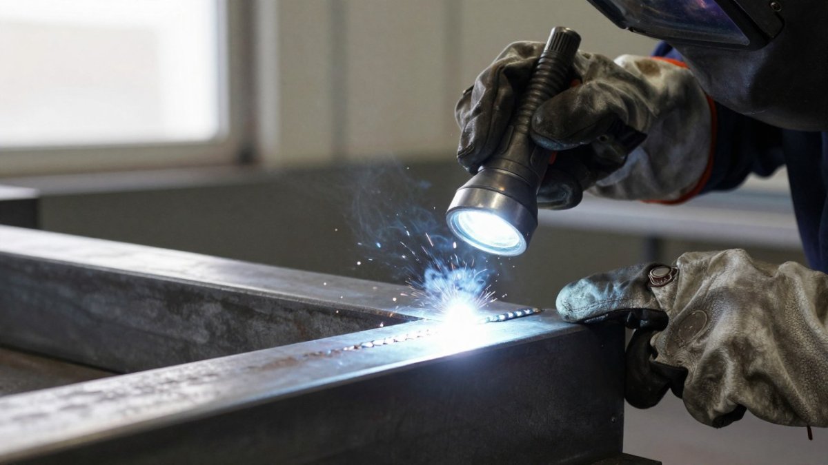
The most common visible signs include:
- Uneven bead width: The weld rises, falls or changes width along its length.
- Excessive spatter: Metal droplets cling around the joint.
- Dark or heavily oxidized color: Discoloration beyond a light straw tint can point to poor shielding.
- Visible cracks or open seams: Any break in the bead needs immediate attention.
- Pinholes or porosity: Tiny surface holes suggest gas or contamination problems.
- Undercut along the edges: A groove melted into the base metal beside the weld.
A weld that looks clean can still hide lack of fusion inside the joint, so appearance alone does not prove strength.
Step-by-Step Visual Inspection Checklist
Visual inspection is the first filter, not the final verdict. A repeatable sequence keeps you from missing the same defect twice.
- Clean the joint first. Remove slag, spatter, and debris; inspecting over slag is the most common reason a defect gets missed.
- Check lighting and angle. Hold a bright, directional light at a low angle across the bead; raking light reveals cracks, undercut, and toe lines a head-on view hides.
- Measure the bead profile. Confirm bead width and reinforcement are consistent; a bead that rises, falls, narrows, or wanders off centerline signals travel speed or manipulation problems.
- Scan for cracks and open seams. Check the crater, toes, and stop-start points. Any crack is a reject until proven otherwise.
- Look for pinholes and porosity. Small surface holes indicate gas or contamination problems and often repeat along the same stretch of bead.
- Inspect the edges for undercut. Run a finger or fillet gauge along the toe; a groove melted into the base metal beside the weld is undercut.
- Check the base metal around the weld. Look for heat tint, arc strikes, spatter burns, and gouges outside the joint.
- Record and photograph each finding. Note location, size, and type of each defect so the repair team can trace it to a cause.
Acceptable bead appearance varies by process, material, position, and joint type. A TIG bead on stainless, a flux-cored bead on structural steel, and a vertical-up stick weld on pipe all have different acceptable profiles, ripple patterns, and heat tint. Judging every weld against one mental image of a "good" bead is a common inspection mistake.
Watch out: a neat-looking weld can still contain lack of fusion, incomplete penetration, or internal porosity that no surface inspection will reveal. When a weld is safety-critical, code-governed, or carrying cyclic or seismic load, the applicable code and a qualified inspector determine acceptance, and nondestructive testing such as ultrasonic, radiographic, magnetic particle, or dye penetrant testing finds what the eye cannot.
Welding Defects and Their Causes
Most visible defects trace back to a small set of root causes: heat input, travel speed, shielding, cleanliness, and joint fit-up. To learn why these failures show up early in service and how to correct them, read why industrial welds fail prematurely. Connect each visible symptom to the likely cause and corrective action so the next pass does not repeat the failure. The matrix below outlines a common troubleshooting sequence for a suspect weld.
| Visible symptom | Likely cause | Corrective action |
|---|---|---|
| Pinholes or porosity clustered along the bead | Contaminated base metal (oil, paint, rust, moisture), wet electrodes, or inadequate shielding gas flow | Grind back to clean metal, dry or re-bake electrodes per the manufacturer's spec, check gas flow rate and hoses for leaks, and verify the nozzle is not clogged with spatter |
| Porosity in a worm-like trail | Excessive travel speed or a long arc that lets the shielding envelope break down | Slow the travel speed, shorten the arc, and confirm the gas cup size suits the joint |
| Slag inclusions between passes | Poor interpass cleaning or a weaving technique that folds slag into the puddle | Chip and brush each pass fully, adjust electrode angle, and avoid excessive weave width |
| Lack of fusion at the sidewall | Heat input too low, travel too fast, or the arc aimed at the center of the joint instead of the sidewall | Raise amperage within the procedure's range, slow travel, and direct the arc at the fusion line |
| Lack of penetration at the root | Joint gap or root opening too tight, root face too thick, or travel speed too high | Open the root gap, reduce the root face, and confirm the procedure's root pass settings |
| Undercut along the toe | Current too high, travel too fast, or an incorrect torch or electrode angle | Reduce amperage, slow travel, and hold a work angle that keeps the arc on the puddle rather than the base metal |
| Burn-through on thin material | Excessive amperage, travel too slow, or insufficient heat sinking | Reduce amperage, increase travel speed, and clamp a heat sink behind the joint |
| Convex, ropey fillet bead | Travel too slow, current too low, or the electrode dragged rather than pushed | Raise current slightly, increase travel speed, and adjust the work angle to flatten the profile |
| Excessive spatter | Current or voltage outside the recommended range, damp electrodes, or a poor ground | Reset to the manufacturer's recommended parameters, use dry electrodes, and clean the ground clamp contact point |
| Dark, heavily oxidized color on stainless | Shielding gas coverage lost or heat input too high | Increase gas flow, shorten the arc, and reduce amperage or use a backing purge where the procedure calls for it |
Porosity forms when gas trapped by the shielding envelope cannot escape before the metal freezes, which is why moisture, oil, and a broken gas envelope all produce the same pinholes. Lack of fusion happens when the puddle does not reach the melting point of the base metal at the joint face. Slag inclusions occur when flux or oxide is trapped between passes, which is why interpass cleaning matters more than any single setting.
Watch out: a defect that looks cosmetic, such as a slightly convex fillet, can hide lack of fusion at the root, so treat the matrix as a starting point rather than a diagnosis. When a defect repeats across a production run, the cause is usually in the procedure or fit-up rather than the welder's hand.
Burn-Through and Fillet Weld Defects to Watch For
Burn-through happens when too much heat melts completely through thin material, leaving a hole or sagging bead on the back side. It is common on thin sheet metal and usually points to excessive amperage or slow travel speed.
Fillet welds, the triangular welds joining two surfaces at an angle, have their own common defects: uneven leg lengths, undercut at the toe, and convex bead profiles that trap stress.
Frequently Asked Questions
What are the signs of bad welding?
Bad welding usually shows up as visible irregularities: an uneven or ropey bead, spatter scattered around the joint, porosity (small holes or pinholes on the surface), undercut along the edges of the weld, and cracks or open seams. Inconsistent bead width and height also point to poor technique or unstable settings. Visual signs alone do not prove a weld is structurally sound, so a weld that looks clean may still need testing if the joint carries load or safety-critical service.
Can a weld look good but still be weak?
Yes. A weld can have an attractive, evenly shaped bead while hiding lack of fusion or lack of penetration beneath the surface. These defects sit inside the joint and are not visible from outside. Slag inclusions and internal porosity can also be hidden. For critical work, visual inspection should be combined with non-destructive testing such as ultrasonic or radiographic testing, performed to the acceptance criteria specified for the project.
What causes cracks in a weld?
Cracks often come from rapid cooling, high restraint in the joint, hydrogen from moisture or contaminated filler, or an incorrect filler metal for the base material. Cracks may appear along the weld centerline, at the toe, or in the heat-affected zone. Any visible crack is a rejectable defect in most codes, and the weld should be removed and redone after the cause is corrected, such as preheating, drying electrodes or adjusting heat input.